3. To measure the excursion distance of each string in both horizontal and vertical directions required constructing a set of contacts that could be moved a known, but small distance from the string. The arrangement used has a gold-flashed contact mounted in a closed-cell neoprene rubber support that offers high flexibility without a tendency to vibrate.
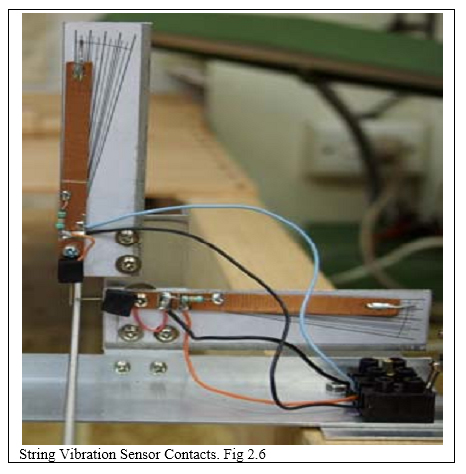
The rubber support is glued to a lever such that the overall length (contact point to end of lever) is 100mm, with a hole drilled 20mm from one end. This gives a 4:1 scale, which was developed on computer and glued to a backing. The scale is in 0.4mm increments, allowing a resolution of 0.1mm.
4. The electrical circuit comprises a 12V DC plug pack with the negative terminal connected to the string under test. The positive terminal connects to each contact via an 82k ohm resistor. The probes of a dual channel digital storage oscilloscope connect across each resistor. When the string is struck, it will vibrate and if the contacts are close enough to the string, an electrical contact is made each time the string hits the contact. This causes the signal to pulse towards zero, which triggers the ’scope, allowing it to record the sequence of pulses from both sensing contacts. These are called H and V in this document.